Explain bridge rectifier with circuit diagram Bridge rectifier wiring diagram Bridge rectifier circuit diagram explained
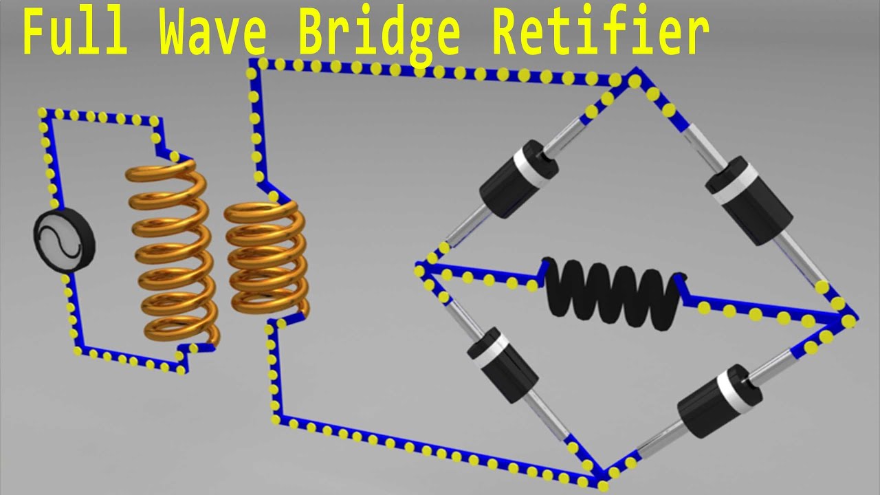
Full Wave Rectifier Bridge Rectifier Circuit Diagram With Design Theory
Bridge rectifier circuit diagram Full bridge rectifier circuit diagram The full-wave bridge rectifier
Bridge rectifier circuit diagram with working
Rectifier bridge circuit diagramBridge rectifier : circuit diagram, types, working & its applications 13+ bridge rectifier schematicRectifier circuit applications operation.
Simple bridge rectifier circuitFull wave bridge rectifier circuit diagram (4 diagrams) Simple bridge rectifier circuitRectifier circuit circuits current alternating relay convert.

Rectifier bridge circuit diagram phase voltage full pulse output diode six rectification angle firing wave half dc current diodes motor
Full wave rectifier bridge rectifier circuit diagram with design theoryElectronics bridge rectifier circuit diagram Full-wave bridge rectifierBridge rectifier ic circuit diagram.
Why is this ideal diode bridge rectifier simulation in ltspice notRectifier circuit bridge diagram working operation theory ac supply transformer 12v circuits electrical types step down use Bridge rectifier circuit diagram and waveformBridge rectifier circuit diagram.

Bridge rectifier : circuit diagram, types, working & its applications
Rectifier circuit circuitsRectifier bridge pcb diodes Bridge rectifier circuit diagram with working.
.


13+ Bridge Rectifier Schematic | Robhosking Diagram

Full-Wave Bridge Rectifier - YouTube

Bridge Rectifier Wiring Diagram - Organicic

Full Wave Rectifier Bridge Rectifier Circuit Diagram With Design Theory
Bridge Rectifier Circuit Diagram With Working

Full wave bridge rectifier circuit diagram (4 diagrams) - Working principle

Why is this ideal diode bridge rectifier simulation in LTSpice not

Simple Bridge Rectifier Circuit

Bridge Rectifier Circuit Diagram And Waveform
